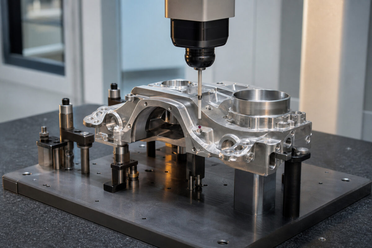
Walk into most manufacturing quality labs and you will find meticulous documentation: first article inspection reports, capability studies, and gauge R&R paperwork. What you seldom find is a formally reviewed, version-controlled, independently verified CMM programme. The code sits on a machine hard drive, written by an operator, accepted on faith, and run for years without anyone challenging its engineering assumptions.
That routine makes the pass-fail call on thousands of parts. It is an unreviewed engineering decision repeated every cycle. Across two decades auditing dimensional metrology in automotive and aerospace plants, I have seen this pattern consistently. The part programme is treated as a tool setup rather than an engineering deliverable, completely bypassing the design review rigor applied to gauges.
The danger is precisely this silence. A faulty mechanical gauge reveals itself through drifting readings and operator complaints. A faulty CMM programme does none of that. It produces consistent, professional-looking numbers derived from a precision machine. The consistency is real, but the trustworthiness is not. A systematic error will confidently reject good parts and accept bad ones until a field failure forces an investigation.
Datum Alignment and the Silent Geometric Shift
Datum alignment is where most CMM programmes fail, and where the geometric consequences are largest. The error mode is structural: the programme establishes a datum reference frame that does not match the functional intent of the drawing. Every subsequent measurement taken in that misaligned frame inherits the mathematical mismatch, shifting results by the full tolerance band.
Consider a planar datum surface specified with a tangent plane modifier. If the programmer uses a standard best-fit alignment, the software averages the surface. A tangent plane requirement, however, must contact only the highest points. The resulting coordinate systems will differ by the exact flatness deviation of the surface itself. Downstream features evaluated in this floating frame are measured against a phantom part geometry.
Another frequent failure involves datum simulator constraint hierarchy. A true datum reference frame requires specific degrees of freedom: primary constrains three, secondary constrains two, tertiary constrains one. Programmes that apply a simultaneous least-squares fit across all datum features abandon this hierarchy. The alignment floats dynamically, and the coordinate system has no physical counterpart on the physical inspection fixture.
Best-Fit Alignment Versus Tangent Plane Constraint
Programmer uses best-fit
- Software mathematically averages the entire datum surface
- Coordinate origin sits at the statistical mean of the points
- Alignment shifts by the total flatness deviation of the surface
- Downstream measurements evaluate geometry against a phantom plane
Drawing requires tangent plane
- Simulation must contact only the highest physical points
- Coordinate origin locks to the functional mounting plane
- Alignment reflects actual part interaction in the assembly
- Downstream measurements inherit the correct functional relationship
Probe Compensation Vector Errors
Probe tip compensation is built into every modern CMM controller, which is exactly why it is dangerous. The software applies a coordinate correction based on the assumed normal vector of the surface at the contact point. If the programmed vector is wrong, the compensation is applied in the wrong direction. The reported point location shifts tangentially rather than radially.
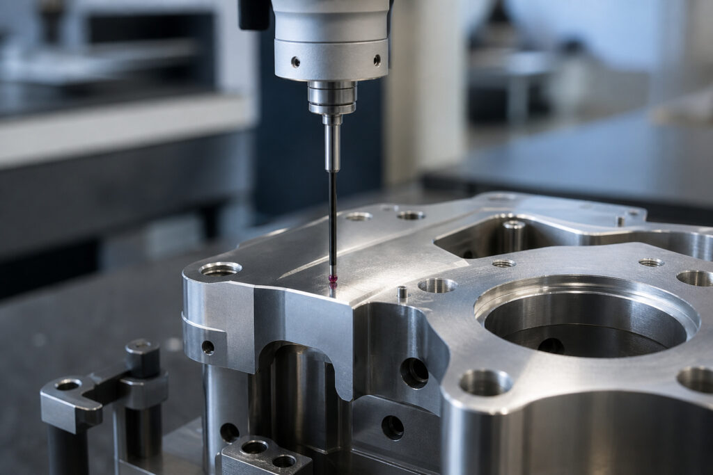
This is not a marginal measurement error. On a cylinder approached with an incorrect vector, the point shift can be several times the probe tip radius. The failure becomes acute on freeform surfaces where the programme uses a nominal CAD model to generate touch vectors. Because the physical part is always located imperfectly, the actual surface sits at a slightly different position than the CAD model predicts.
The probe approaches using the nominal CAD normal, contacts the real surface at a different angle, and the compensation vector diverges from the true normal. Calibrating the probe tip does not solve this. Calibration establishes the effective tip radius and stylus offset; it does nothing to correct a compensation vector pointing the wrong direction. The result is a computed feature that is an artefact of the software logic.
Sampling Density and the Illusion of Coverage
A CMM does not measure a physical surface. It measures a finite set of discrete points and constructs a mathematical representation. The gap between that mathematical representation and the actual surface is a function of sampling density, point distribution strategy, and the actual form error present on the real part.
Programmes that use sparse point counts on surfaces with meaningful form deviation are not measuring the feature. A flatness callout evaluated from four points tells you almost nothing about the surface geometry. It confirms only that four specific locations happen to lie near a common plane. A cylindricity check based on a single circular scan at one height reports the roundness of that specific cross-section, not the geometry of the cylinder.
Scanning probes have not solved this problem completely. A scanning head collects high-density data along its path, but the path itself is still programmed. If the scan path under-samples the ends of a cylinder where taper and bell-mouthing occur, the density along the path is irrelevant. The unmeasured regions remain unmeasured, and the reported value describes the path, not the physical part.
How Evaluation Logic Masks Defects
The mechanism by which a bad programme accepts a defective part is rarely dramatic. There is no alarm or out-of-tolerance flag. The defect exists on the hardware, but the measurement strategy either does not intersect the defective region or evaluates the result in a way that mathematically averages the defect below the detection threshold.
Quality systems rigorously review gauge designs but skip the equivalent rigour for CMM code.
Evaluation method is the other half of the problem. A profile tolerance requires that every point on a surface lie within the tolerance zone relative to true position. Programmes that evaluate profile based on the best-fit condition of measured points, rather than the worst-case point, report a value better than the actual surface achieves. The same applies to position callouts using maximum material condition bonuses without verifying the actual mating envelope.
The result is a class of defect that exists on the hardware, passes inspection, and is discovered only at assembly. By then, the programme has been the basis for acceptance decisions across a production run. The root cause investigation leads back to a measurement routine that was never peer-reviewed, never version-controlled, and never validated against a known-defective master.
Establishing Programme Integrity
Fixing this requires treating the CMM programme as a strictly controlled engineering document. This means a formal review of datum alignment logic against the drawing's datum scheme, verification that approach vectors match the actual geometry of each measured feature, and documented justification for the sampling strategy on every controlled characteristic.
Validation requires a known-defective part. Every production programme should be challenged against a master part containing a specific, characterised defect in each controlled feature. If the flatness report stays clean on a part with a measured high spot, the programme is not fit for purpose. This is the measurement equivalent of an MSA study, testing detection capability rather than mere repeatability.
CMM Programme Validation Workflow
- 01Drawing ReviewTrace datum scheme, modifiers, and tolerance boundaries to verify programming assumptions.
- 02Logic VerificationConfirm vector compensation directions and sampling density match the geometric feature.
- 03Defect ChallengeRun the programme against a known-defective master part to prove detection capability.
- 04Version ControlLog, review, and formally approve all code changes before releasing to production.
Configuration Control and Revision Management
The worst variant I encounter is the inherited programme that nobody has revisited against the current drawing revision. Engineering changes accumulate silently. A datum scheme correct against drawing revision C may be flatly wrong against revision F, particularly when datum targets have been redefined or a datum feature has been reclassified.
The CMM programme continues to run because it produces numbers, and those numbers fall inside tolerance. The discrepancy surfaces only when a customer's inspection laboratory reports different results on the same parts. This scenario immediately triggers supplier escalation, 8D containment, and severe scrutiny of the entire quality management system.
Version control is the final structural layer. When a drawing revises, the CMM programme must be re-validated. When a programme is edited, even a seemingly trivial change to a touch point count or an approach vector, the revision must be logged, reviewed, and approved before release. Treat the programme file with the exact discipline applied to a CNC machining programme or a fixture drawing.