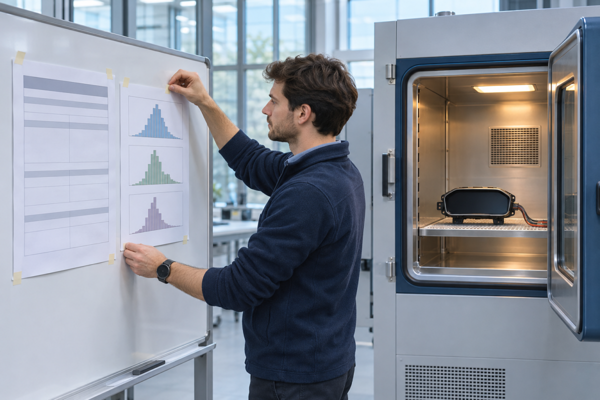
Walk through most environmental labs and you will find chambers running profiles that bear little resemblance to anything the product will experience in service. A dashboard component destined for a temperate European fleet cycles between minus forty and plus one hundred twenty degrees because the standard says so. A gearbox ECU gets vibration along a flat random spectrum when its real life is spent at a handful of discrete engine orders. Nobody is cheating; the specifications are simply old, inherited, and unexamined.
I have spent years unpicking test programmes like these, and the pattern is remarkably consistent. Over-testing is rarely a deliberate choice. It accretes: a margin added by a customer, another by the supplier's reliability engineer, a third by the lab interpreting an ambiguous clause. The result is a product designed, validated and costed against an environment that does not exist.
Worse, over-testing actively hides real failure modes. A part that survives a brutal but irrelevant thermal shock may still fail from humidity cycling, condensation, or a slow diurnal swing that the accelerated profile never reproduces. The fix is unglamorous and well established: build a mission profile, derive the test from it, and correlate what you test against what the field returns. The rest of this article is how I do that in practice.
Building the Mission Profile
A mission profile is a quantitative description of the environments your product experiences across its duty cycle, weighted by exposure. Not the worst case anywhere on Earth — the distribution of cases your population actually sees. For an engine-mounted sensor, that means thermal soaks at key-off, cold starts in winter, under-bonnet temperatures at motorway cruise versus city idling, splash and road-grit exposure, and the vibration signature of the specific powertrain, not a generic one.
Data sources matter here. Climate data is available in fine granularity from meteorological services; fleet telemetry, where the customer permits access, gives real temperature histograms rather than assumed ones. Where telemetry is unavailable, instrumented vehicles are worth the effort: a thermocouple harness and a logger on a handful of representative vehicles for a full seasonal cycle will teach you more about the real thermal duty than any specification document. For vibration, accelerometer measurements at the actual mounting location, across the operating envelope, beat any table of generic spectra.
The profile must distinguish between storage, transport and operation. A component can be qualified to a mild in-service environment and still be destroyed by the intercontinental shipping leg: container temperatures, salt-laden marine air, drop shocks at the freight handler. I have seen more field returns traced to transport than to any inadequacy in the in-service qualification. Write the transport environment into the profile explicitly, with measured container data if you can get it.
How Margins Compound Into Nonsense
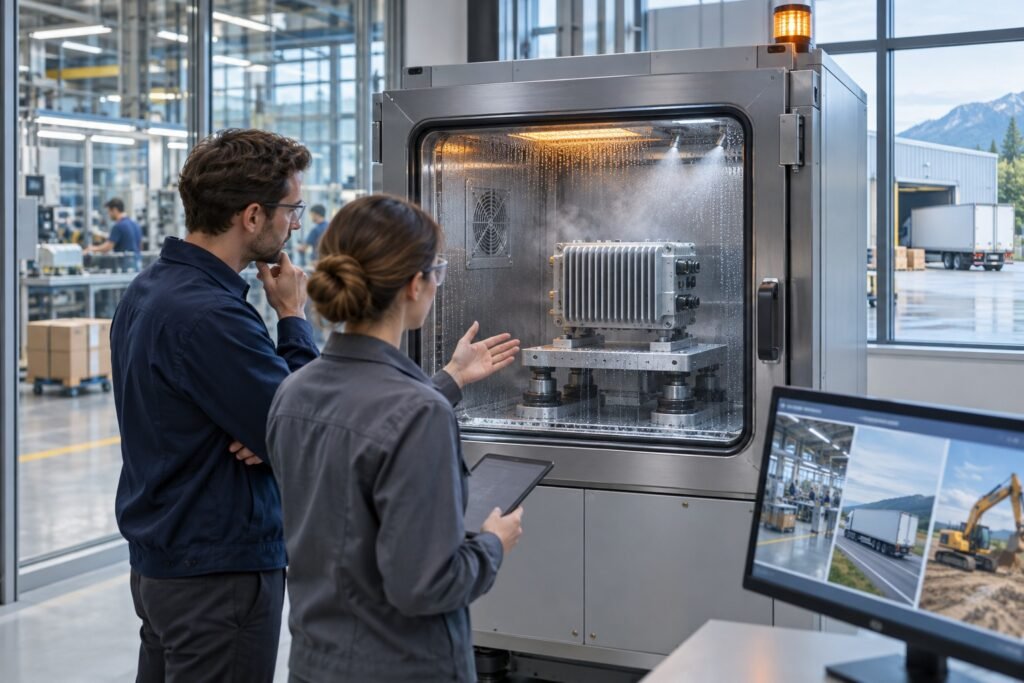
Over-testing deserves scrutiny because its costs are silent. Every unnecessary ten degrees of thermal range forces material selection, seal design and connector ratings up a grade. Every dB of over-specified vibration demands stiffer brackets, heavier housings, more potting compound. The product gets heavier, dearer and often worse: stiffer housings transmit rather than absorb shock, and over-designed thermal margins consume cost or packaging budget needed elsewhere.
The mechanism is margin stacking. The customer specification already contains tail-case margin. The supplier adds a factor for test-to-test variation. The lab adds setup conservatism. Each addition is individually defensible; collectively you may be qualifying a door module for Antarctic conditions when its fleet never leaves the Iberian peninsula. When I audit test derivations, I trace every factor back to its origin and ask who owns it. Unowned margins get removed; owned margins get justified in writing.
There is a subtler problem: over-testing to an irrelevant profile consumes test time and sample count that should be spent on the relevant one. A programme that burns weeks on extreme thermal shock has often done no humidity bias testing, no condensation cycling, no salt fog — precisely the environments that produce the warranty claims. Fatigue from an artificial spectrum tells you nothing about fatigue from the real one if the damage spectra do not match. Time is not the issue; allocation is.
Margin Stacking in Test Derivation
What teams do
- Copy tail-case limits from the customer spec
- Add a factor for lab-to-lab variation
- Add setup conservatism at the chamber
- Round the profile up to the next standard test
- Never revisit the compounded result
What works
- Trace each margin to a named owner
- Remove margins nobody can justify
- Derive levels from measured field data
- Validate the accelerated failure mode matches service
- Reassess the profile at every design milestone
Tailoring the Test: Derivation, Not Copying
Once the mission profile exists, the test profile is derived from it, and the derivation must be documented. Thermal cycling durations come from counting the equivalent damaging cycles in the profile — the number of in-service transitions exceeding a relevant temperature delta, converted through a Coffin-Manson relationship for solder joints and bonded interfaces, or through measured coefficients of expansion for mechanical joints. Dwell times, ramp rates and cycle counts all trace back to field data or justified engineering assumptions.
Vibration tailoring follows the same logic. Convert the measured duty-cycle spectrum into a test spectrum using a damage-equivalence approach — Miner's rule on a fatigue-relevant basis, typically via a finite-element model or measured transmissibility to identify the fragile frequencies. Then compress time by increasing levels within the constraint that the failure mode you accelerate remains the one that would occur in service. If raising the level changes the mode from solder fatigue to wire breakage, you have stopped testing your product and started testing a fiction.
Humidity and corrosive environments need equal care. The 85/85 steady-state condition is ubiquitous and largely useless for products whose real exposure is cyclic condensation — temperature swings that take surfaces below the dew point. Condensation cycling, with bias voltage applied to the device under test, reproduces electrochemical migration, dendrite growth and connector corrosion far more faithfully. Match the mechanism, not the chamber's default recipe.
From Field Environment to Chamber Condition
- 01Measure the duty cycleInstrumented vehicles, telemetry, mounting-location accelerometers
- 02Build the mission profileExposure-weighted environments for storage, transport and operation
- 03Derive the test profileDamage-equivalent cycles and spectra, documented acceleration models
- 04Verify the mechanismConfirm the accelerated failure mode matches the service failure mode
- 05Correlate with field returnsFeed warranty data back and revise the profile
What to Measure During the Test
Chamber setpoint is not product response, and confusing the two invalidates everything downstream. Thermocouples or RTDs on the product itself — at the hottest and coldest anticipated points, plus a control location — tell you whether the dwell was long enough for the part to actually reach temperature. A chamber that dwells thirty minutes while the internal mass of the module lags forty degrees behind has tested nothing but the air. I insist on product-response traceability in every report.
For vibration, control the spectrum at the fixture interface and monitor response at the critical locations on the unit. Fixtures are where good tests die: a resonance in the mounting plate can amplify or notch the spectrum seen by the part. Fixture transmissibility must be verified bare before the test, and any resonance outside acceptable limits designed out. Accelerometers at candidate failure sites — connector legs, large PCB spans, heavy components — turn the test from pass/fail into a measurement.
Continuous electrical monitoring matters more than end-of-test functional checks. Intermittent failures under thermal ramp — a cracked solder joint making and breaking contact, a connector fretting open — are invisible to a functional test performed at ambient after the profile completes. Monitor continuity, supply current and key signal paths in real time throughout the profile, and time-stamp every anomaly against the environmental condition. That time stamp is what lets you diagnose the mechanism later.
If raising the test level changes the failure mode from solder fatigue to wire breakage, you are no longer testing your product.
Correlation With the Field
The test programme is not finished when the report is signed; it is finished when field data confirms it. Every warranty return and every field failure investigation should feed back into the mission profile and the test derivation. When a validated part fails in service, one of two things is wrong: the test did not reproduce that environment, or the part tested was not representative of production. Both are findings about the programme, not just the part.
Formal correlation requires discipline. Build a failure-mode register that maps each field failure to the test that should have caught it and the test that actually could have caught it. Over a product generation or two, patterns emerge: the recurring escapes cluster around condensation, salt exposure, combined vibration-and-temperature loading, or long-duration low-level phenomena that acceleration destroys. Those clusters tell you precisely which profiles to revise and which margins to redistribute.
Combined environment testing deserves more use than it typically gets. Real duty cycles impose heat, vibration and humidity simultaneously, and the interactions are not additive: a connector fretting under vibration while thermally cycling fails far sooner than the sum of the individual tests suggests. Running combined profiles, where the chamber and shaker are integrated, is costlier per hour but cheaper per discovered failure mode. I treat sequential single-environment testing as a screening tool and combined testing as the qualification of record for anything safety-relevant.
Governing the Programme
Test tailoring only survives scrutiny if it is written down. I require a test derivation document for every qualification: the mission profile with its data sources, the acceleration models used with their assumptions and validity limits, the margin applied at each stage with the owner named, and the trace from field environment to chamber condition. When a customer challenges a reduced test, that document is the answer. When a field failure questions an approved test, that document is where the investigation starts.
Review the programme at design milestones, not just at test readiness. The mission profile drafted at concept stage, from assumed data, must be refreshed as instrumented-vehicle data, supplier measurements and early field experience arrive. A profile frozen at project start is a hypothesis; the mature programme treats it as one. Where the data changes the profile, the delta between what was tested and what is now understood must be assessed — retest the difference, not everything.
Finally, keep the lab honest. Witness the setup, verify the fixture, review the calibration status of the control instrumentation, and read the raw logs rather than the summary. The best derivation in the world is worthless if the chamber overshoots by fifteen degrees on every ramp or the shaker control notches at two hundred hertz. Environmental testing is engineering, not ritual — and rituals, left unexamined, will happily qualify your product for a world it will never see.