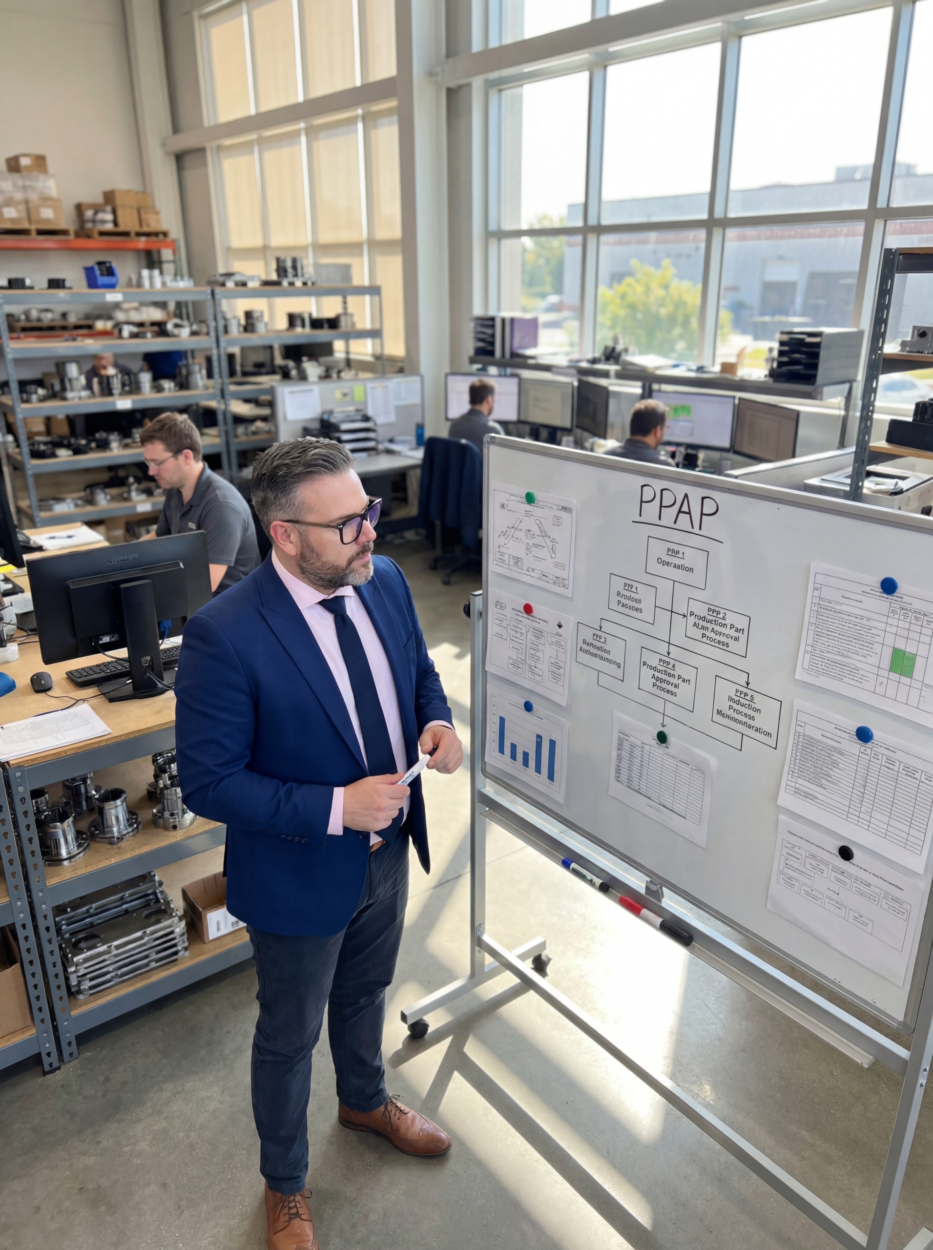
PPAP is the automotive industry's mechanism for proving that a supplier understands a customer's requirements and can meet them consistently in serial production. It is governed by the AIAG core tools manual and mandated by IATF 16949. When a supplier submits a PPAP package, they are making a verifiable claim: the process is stable, the measurement system is valid, and the part will conform to specification on run number one and run number ten thousand.
I encountered the reality of this process early in my career while working with a supplier of brake system components. The production director wanted to ship parts immediately. He could not. The OEM required a full PPAP approval before granting access to the assembly line. Without that signed Part Submission Warrant (PSW), the parts were scrap metal regardless of how well they were manufactured. The approval process is not paperwork; it is the operational gate that de-risks the entire supply chain.
Treating PPAP as a documentation exercise is the fastest route to a field failure. Every element in the package exists to close a specific gap between design intent and manufacturing reality. Skipping or superficially completing these elements leaves latent defects in the process. When production scales, those defects become warranty claims, recalls, and stopped production lines.
The Architecture of the 18 Required Elements
A complete PPAP package consists of 18 elements that link design intent to manufacturing execution. Elements 1 through 3 establish the baseline: design records, engineering change documents, and customer engineering approval. If there is ambiguity in the drawing tolerances or unapproved deviations, the entire submission is invalid. The supplier must manufacture against a frozen, unambiguous specification.
Elements 4, 5, 6, and 7 form the risk mitigation core. Design FMEA identifies potential failure modes in the product itself. The Process Flow Diagram maps every step of manufacturing. Process FMEA analyses what could go wrong at each of those steps. The Control Plan then dictates exactly how you will prevent or detect those failures. These four documents must be tightly cross-referenced. A characteristic flagged as high-risk in the PFMEA must have a specific, defined control method in the Control Plan.
The remaining elements validate the measurement and production systems. Measurement System Analysis (MSA) proves your gauges are capable. Initial Process Studies demonstrate that the process can hit Cpk targets. Material and performance test results verify mechanical properties. The final element, the Part Submission Warrant, is the signed declaration that all other 17 elements are accurate and available for audit.
Submission Levels: Matching Evidence to Risk
PPAP is not a one-size-fits-all package. The AIAG manual defines five submission levels, and the OEM dictates which level applies based on part criticality, supplier maturity, and historical performance. Level 3 is the industry default. It requires the supplier to submit the PSW, sample parts, and the complete documentation of all 18 elements to the customer for review.
Level 1 is the lightest, requiring only the PSW warrant. Level 2 adds product samples to the warrant, though the customer typically retrieves them from the supplier's facility. Level 4 and Level 5 shift the burden of evidence. At Level 5, the supplier retains all parts and documentation on-site, and the customer conducts a physical audit at the supplier's plant to verify compliance. This level is typically reserved for high-risk commodities or new suppliers.
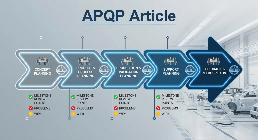
Understanding the required level early in the Advanced Product Quality Planning (APQP) phase is critical. If you plan for a Level 3 submission but the customer requires Level 5 on-site verification, your timeline will collapse. The physical layout of your facility, the accessibility of your records, and the readiness of your master samples all become immediate audit factors.
Capability Targets and Measurement Validation
Core PPAP Statistical Thresholds
Cpk is the headline number in any PPAP submission, but it is entirely dependent on the validity of the MSA. If your gauge cannot reliably distinguish between good and bad parts, your capability index is a mathematical fiction. I have audited plants where operators were using uncalibrated fixturing to measure tight tolerances. The Cpk looked exceptional, yet the parts failed entirely at the customer's assembly plant.
Before calculating Cpk, you must conduct a Gauge Repeatability and Reproducibility (GR&R) study. The acceptable threshold is typically under 10% of the study variation. If the gauge fails, you must redesign the fixturing, change the measurement method, or use a different instrument. Only when the measurement system is proven capable can you trust the dimensional results and process capability data that follow.
Process Discipline Over Prototype Optimism
A PPAP submission is only valid if the parts are manufactured under actual serial production conditions. This means using the final production tooling, the actual production operators, and the documented cycle times. One of the most frequent and fatal errors suppliers make is building the PPAP sample parts during a slow, carefully controlled prototype run, rather than at the actual production rate.
A capability index calculated on prototype parts built during an unhurried run is a mathematical fiction that hides serial production failures.
When production scales up, the process dynamics change. Cycle times compress, tooling heats up, and operators introduce variability. If the PPAP parts were built in an artificial environment, the process will not hold its tolerances during serial runs. The initial process study must capture the natural variation of the real manufacturing process, or the approval means nothing.
Suppliers must also rigorously manage Customer Specific Requirements (CSRs). Every OEM interprets the IATF 16949 standard slightly differently. Some require specific software formats for 3D measurement data. Others demand unique symbols on engineering drawings or additional testing for material certification. Missing a CSR detail will result in a rejected PPAP, even if all 18 base elements are technically correct.
The Linkage Failure: FMEA and Control Plans
The most common structural failure in a PPAP package is the disconnect between the DFMEA, PFMEA, and Control Plan. These documents are frequently written by different people at different times and treated as standalone files. When they are not linked, high-risk failure modes identified in the FMEA phase go uncontrolled on the shop floor. The Control Plan ends up checking generic dimensions rather than mitigating actual risks.
The PPAP Risk Mitigation Chain
- 01DFMEA IdentificationPotential failure modes and their effects on the end user are identified.
- 02Process FMEA TransferDesign risks are mapped to specific manufacturing operations that could cause them.
- 03Control Plan DefinitionSpecific measurement methods, sample sizes, and reaction plans are assigned.
- 04Shop Floor ExecutionOperators follow the control plan, closing the loop between risk and reality.
When I managed a complex electronic control unit submission, the initial documentation was over three hundred pages of disconnected data. We halted the submission and rebuilt the linkage. Every Critical Characteristic (CC) flagged in the Design FMEA was explicitly transferred to the Process FMEA. From there, each characteristic required a specific control method, sample frequency, and reaction plan in the Control Plan.
This linkage is what auditors look for first. If a safety-critical characteristic has no defined reaction plan in the Control Plan, the PPAP will be rejected. The documentation must prove that the engineering team identified the risk, the quality team planned for it, and the production team has the tools to contain it if the process drifts out of control.
Application Beyond Automotive Manufacturing
The discipline of PPAP is not exclusive to IATF 16949 automotive suppliers. The core methodology, proving process capability and risk mitigation before mass production, is highly effective in any industry where component failure poses a safety or liability risk. Aerospace, medical devices, and defence manufacturing all rely on variations of this approval architecture.
In aerospace, the AS9100 standard relies on First Article Inspection (FAI) per AS9102, which mirrors the dimensional validation elements of PPAP. The FAA's 14 CFR Part 21 certification processes demand rigorous proof of conformity. Medical device manufacturers operating under FDA 21 CFR Part 820 and ISO 13485 must execute Design Transfer protocols that function identically to a PPAP run, proving that production can reliably meet design outputs.
The vocabulary changes, but the mechanism remains. Whether the trigger is an automotive launch, an aerospace certification, or a medical device validation, the requirement is the same: prove your process is stable, prove your measurement is valid, and prove your risk mitigation is active on the shop floor. When done correctly, part approval is not bureaucracy; it is the foundation of manufacturing trust.