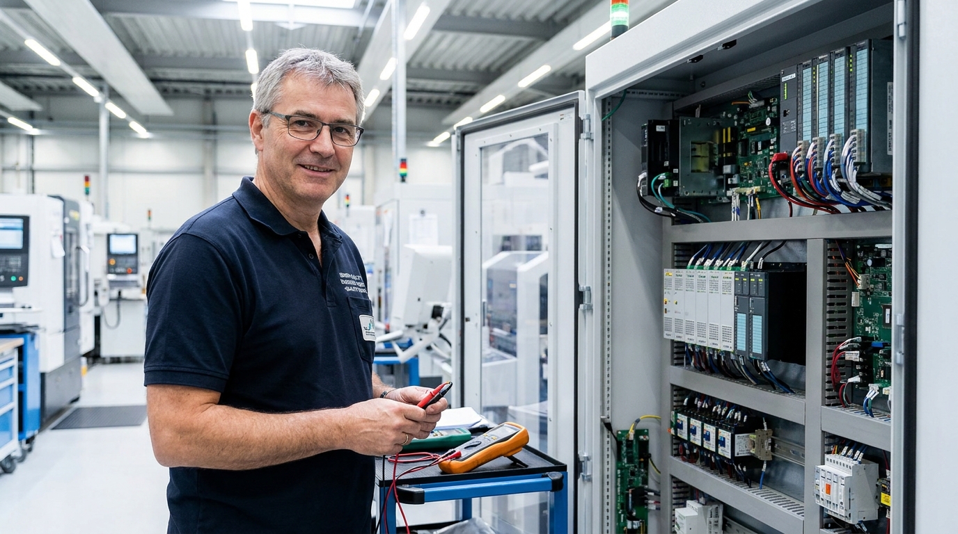
A machine stops. The maintenance technician diagnoses a failed sensor within five minutes. The repair itself takes less than ten. But reaching the sensor requires removing three guards and fourteen fasteners, extracting an entire sub-assembly, and reassembling it afterwards. Two hours of production lost to a five-minute component swap.
Now picture a different machine with identical functionality. The designer placed that same sensor behind a single hinged panel. The entire intervention takes seven minutes. This is the operational difference between a product engineered for function and a product engineered for Design for Maintainability (DfM).
DfM is a systematic approach to product and system design that mandates serviceability as a core requirement. Most engineering teams optimise for aesthetics, unit cost, and assembly efficiency. DfM forces them to optimise for the technician who will service the equipment three years into its lifecycle. In high-stakes manufacturing, ignoring this principle burns millions in unplanned downtime.
The Lifecycle Cost Reality
The maintenance cost of a complex product over its lifecycle frequently exceeds its initial purchase price. In aerospace (AS9100 environments), the ratio of acquisition cost to total lifecycle maintenance cost typically sits between 1:3 and 1:5. For every euro spent buying the asset, expect to spend up to five keeping it running.
Industrial manufacturing faces similar economics. Unplanned downtime in an automotive plant routinely costs between 15,000 and 50,000 euros per minute. When a repair takes two hours instead of twenty minutes simply because a designer ignored access paths, that geometric decision has directly cost the operation millions of euros.
Industry studies consistently show that 60 to 80 percent of maintenance time is spent accessing the repair point, not executing the repair. Disassembly, reassembly, retrieving tooling, and navigating physical obstructions dominate the intervention. That is not maintenance work; it is pure process waste.
Core Principles of Maintainable Design
DfM is not a single technique but a framework of design rules. The first is accessibility. If a component requires periodic inspection or replacement, the design must provide rapid, safe access. The rule of thumb is absolute: if physical access takes longer than the actual repair, the design has failed.
The second principle is modularity. When a specific function fails, the technician should swap a standardised module, not dismantle half the system. A modular design uses uniform fasteners, identical connectors, and standardised mounting interfaces. It eliminates the special tools and proprietary components that bottleneck spare parts inventory.
The third principle is diagnosability. Before a technician can repair the equipment, they must identify the failure mode. Precise diagnostics should not require a laboratory. Effective DfM integrates fault codes that carry meaning, hierarchical alarm systems, and built-in test points that guide the technician straight to the root cause.
Monolithic vs. Modular Maintenance Architecture
Monolithic design
- Function spread across multiple nested sub-assemblies
- Requires 15+ fasteners and specialized removal tools
- MTTR measured in hours, blocking production lines
- High risk of damaging adjacent components during access
Modular design
- Function contained in a single, self-contained module
- Secured by standard Torx fasteners and quick-disconnects
- MTTR measured in minutes, restoring OEE rapidly
- Poka-yoke connectors prevent incorrect reassembly
Safety, Tooling, and Error Proofing
Maintenance is one of the most dangerous activities on a shop floor. Statistics indicate that up to 30 percent of industrial workplace accidents occur during maintenance operations. DfM mitigates this by engineering safety directly into the hardware: integrated Lockout/Tagout (LOTO) points, ergonomic access positions, and safe clearances that eliminate the need to work blind in confined spaces.
Every special tool a design requires is a potential delay. A maintainable design standardises tooling across the entire machine. I have audited manufacturing plants where a single production line required 47 different screw types. Standardising down to four sizes reduced maintenance time by 22 percent and cut spare parts inventory by 35 percent.
Finally, effective DfM deploys poka-yoke for service. Technicians are human; they make errors under pressure at 3 AM when the line is down. Connectors must be keyed so they cannot be plugged in backwards. Modules and their corresponding ports must be colour-coded. Mechanical locators must make incorrect assembly physically impossible.
Integrating Maintenance into the Design Process
Implementing DfM requires bringing maintenance technicians into the engineering room. Their input is not an opinion; it is operational data. They know which components fail, how they fail, and how long the repair takes. Designing a new asset without this feedback is designing blind.
A designer who has never watched a technician service their machine cannot design a maintainable product.
Before releasing a design for manufacture, the team must physically simulate critical maintenance operations on a prototype or 3D mockup. Measure the time. Measure the technician's physical movements. If the simulation forces the technician into an unnatural posture to reach a component, change the CAD model immediately.
Apply a strict DfM checklist during design reviews. Does access to the top ten replaced components take under ten minutes? Is LOTO secured at every access point? Can standard maintenance be performed with fewer than five tool types? If the answer is no, the design is not ready for release.
Metrics That Drive Maintainability
What gets measured gets designed. To enforce DfM, engineering teams must track specific metrics across the asset lifecycle. The most critical indicator is Mean Time To Repair (MTTR). If MTTR consistently exceeds the actual component swap time, the physical design is obstructing the technician.
Mean Time Between Maintenance (MTBM) tracks the reliability of the modular components themselves. A low MTBM points to a sourcing or application failure, while a high MTBM proves the design choice was correct. Both metrics must feed back into the APQP process for the next generation of equipment.
Core Metrics for Maintainable Design
Industry 4.0 and Predictive Maintenance
Digital tools amplify DfM principles. A digital twin allows engineering teams to simulate maintenance operations in a virtual environment before the physical asset exists. Technicians can practice complex procedures, identify spatial obstructions, and validate tool clearance in CAD, locking in maintainability before steel is cut.
IoT-enabled diagnostics transform maintenance from guesswork to data reading. Integrated sensors monitor component wear and predict failures, giving maintenance teams the lead time required to order parts and schedule planned downtime. This shifts the operational model from reactive firefighting to planned intervention.
I reviewed a new automotive assembly line design where the engineer placed a critical sensor deep inside the guard structure. The maintenance technician pointed out that accessing it for the mandatory monthly check would require removing the entire top cover. The engineer moved the sensor 15 centimetres outside the guard. One line on the drawing saved 1,200 hours of maintenance labour in the first year alone.
Quality is not just about how well a product functions when it is new. In aerospace and automotive manufacturing, quality is measured by how rapidly and safely an asset can be returned to operation when a component inevitably fails. Design for Maintainability is the engineering discipline that secures that operational readiness.