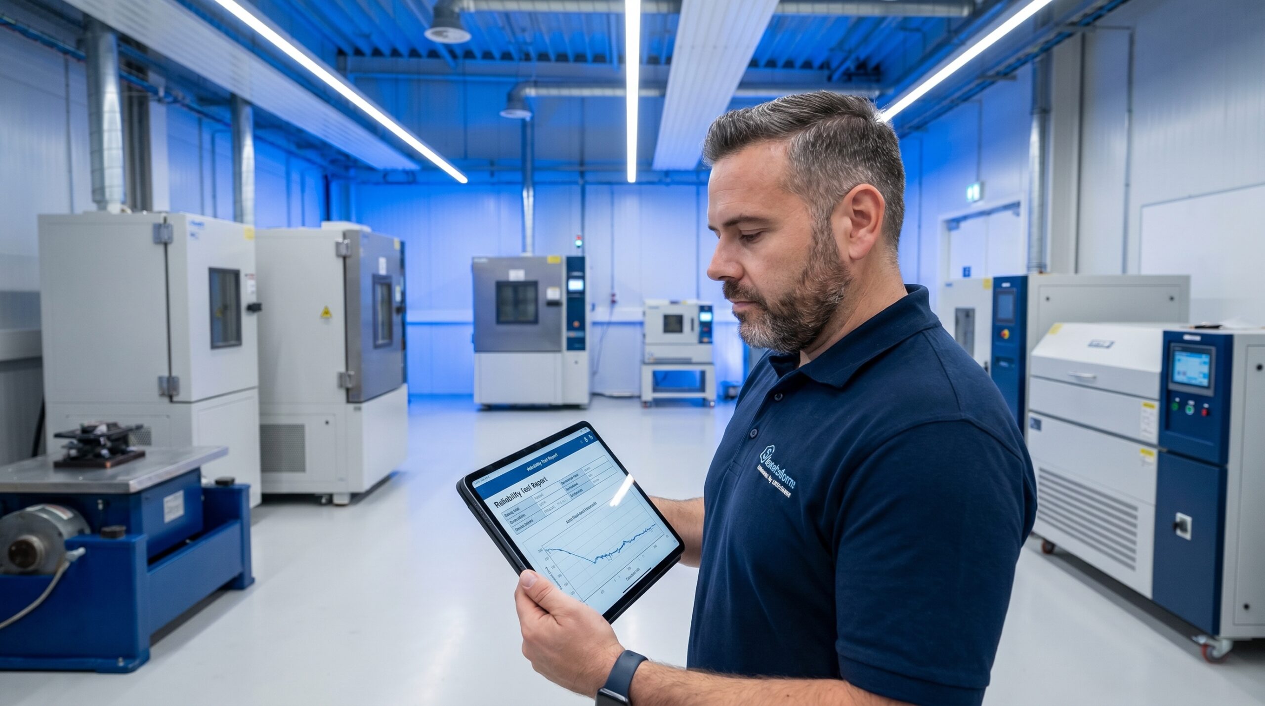
Development teams build prototypes that pass every validation test, secure certification, and enter serial production confidently. Six months later, warranty claims arrive in waves. Customers report identical failure modes that engineers never anticipated during the design phase. The root cause is rarely a manufacturing defect. The failure was designed into the product before the first unit was ever built.
This scenario is standard in organisations that treat reliability as a verification activity performed on finished hardware. Design for Reliability (DfR) shifts that paradigm. It replaces the test-and-fix loop with a systematic effort to understand how and why a product will fail while it still exists only as a concept, engineering the failure modes out before any steel is cut.
In automotive, aerospace, and medical device manufacturing, where field failures carry safety, regulatory, and financial consequences, DfR is an operational necessity. I have audited plants where 8D teams spent months firefighting field issues that a rigorous stress-strength analysis would have caught in a matter of days during the concept phase.
Why the Test-and-Fix Model Fails
Most engineering organisations operate under an illusion of verification. They build a physical prototype, run a battery of tests, and if the hardware survives, they declare the product reliable. This approach collapses under three fundamental flaws that DfR is specifically designed to address.
First, test plans only cover scenarios engineers can anticipate. If nobody modelled the combined effect of thermal cycling, mechanical vibration, and humidity on an electronic control unit over a fourteen-month service life, the test matrix will not include it. The laboratory will pass the part, and the customer will break it.
Second, prototypes do not represent serial production. A prototype is meticulously hand-assembled, inspected, and optimised by skilled technicians. The serial product is the output of a manufacturing process with inherent variation, tooling wear, tolerance stack-up, and human factors. Passing a test on a golden prototype guarantees nothing about the tenth unit off the line.
Third, the cost of design changes scales exponentially. A material substitution in the concept phase costs a fraction of the engineering hourly rate. The same change during physical prototyping forces tooling modifications and re-validation. After market launch, it triggers warranty campaigns, logistics reversals, and reputational damage.
The Five Pillars of Design for Reliability
DfR is not a single tool. It is a system of five interconnected technical pillars that span the entire product lifecycle, integrating reliability decisions into every engineering review. Bypassing any single pillar breaks the feedback loop and degrades the final hardware quality.
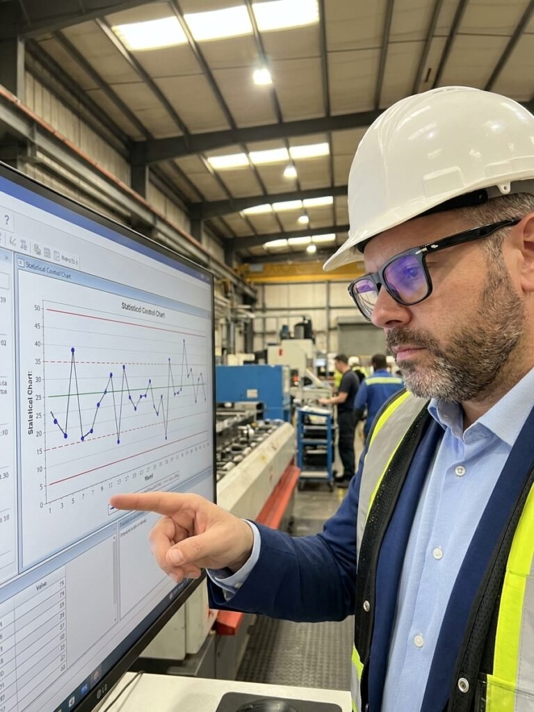
It begins with quantified reliability requirements. This is a business decision, not a technical aspiration. A requirement must be measurable, tied to customer expectations, and mathematically cascaded down to subsystem and component levels. Without a hard target like 99.5% reliability over 10,000 cycles at specified temperature extremes, the DfR process devolves into subjective academic exercises.
The second pillar is early failure analysis. Before a prototype exists, engineers must deploy DFMEA alongside Fault Tree Analysis (FTA) and Reliability Block Diagrams (RBD). Stress-Strength Analysis is particularly critical. By comparing the statistical distribution of anticipated loads against the material strength distribution, engineers pinpoint the exact overlap where field failures will occur.
Virtual simulation forms the third pillar. Finite Element Analysis (FEA) for structural integrity, Computational Fluid Dynamics (CFD) for thermal management, and Monte Carlo simulations for statistical tolerance variation allow teams to test thousands of design iterations cheaply. By the time a physical prototype is built, basic failure scenarios should already be engineered out.
The fourth pillar is targeted physical validation via accelerated testing. Highly Accelerated Life Testing (HALT) pushes prototypes beyond design limits specifically to break them and uncover latent weaknesses. Accelerated Life Testing (ALT) uses models like the Arrhenius equation to extrapolate normal service life from high-stress durations. Highly Accelerated Stress Screening (HASS) applies these principles to serial production to eliminate manufacturing escapes.
The final pillar is the closed-loop feedback system. Field failures must be systematically analysed and fed back into the DFMEA and lessons-learned databases for the next development cycle. Warranty data is not just a financial metric; it is the ultimate validation test report.
Integrating DfR into APQP
In organisations governed by IATF 16949, DfR does not exist in a vacuum. It integrates seamlessly into the Advanced Product Quality Planning (APQP) framework. When mapped correctly, APQP serves as the operational vehicle for DfR execution.
During Phase 1, reliability targets are defined directly from the Voice of the Customer. Phase 2 executes the design work, housing the DFMEA, FTA, and simulation activities. Phase 3 forces the critical handoff to manufacturing, where PFMEA identifies how production variation might degrade the reliability that was engineered into the design.
Phase 4 executes the validation plan via DVP&R (Design Verification Plan and Report), running the HALT and ALT protocols established in earlier phases. Finally, Phase 5 captures field data and warranty analysis. Teams that execute DfR correctly cover APQP requirements naturally. Teams that treat APQP as a documentation exercise build a process without engineering substance.
DfR Execution Within APQP
- 01Define Reliability TargetsTranslate Voice of the Customer into quantified metrics in APQP Phase 1.
- 02Design Analysis & SimulationExecute DFMEA, FEA, and stress-strength modelling during product design in Phase 2.
- 03Process Failure LinkageUse PFMEA in Phase 3 to ensure manufacturing does not degrade designed reliability.
- 04Accelerated ValidationExecute HALT, ALT, and DVP&R reporting during Phase 4 product validation.
- 05Field Feedback LoopAnalyse warranty data in Phase 5 to update lessons learned for the next program.
Common Implementation Failures
Over twenty years implementing quality systems, I have observed three consistent failure patterns when organisations attempt to adopt DfR. These failures stem from a fundamental misunderstanding of what the methodology requires, and they completely neutralise the intended benefits.
The first error is equating DFMEA with the entirety of DfR. A DFMEA is a risk identification tool, not an elimination mechanism. If the failure modes identified in the DFMEA are not subsequently addressed via simulation, material engineering, and physical validation testing, the document is just a list of known risks that the organisation has decided to accept.
The second error is prioritising short-term time-to-market over upfront analysis. Teams claim they lack the time for rigorous simulation and accelerated testing. They launch the product on schedule, and then spend the following six months managing field returns, conducting 8D investigations, and engineering running changes. Skipping DfR does not save time; it simply shifts the effort to the most expensive and disruptive phase of the lifecycle.
Reliability is designed into a product, never inspected into it after the fact.
The third error is assigning reliability ownership to the Quality department. Quality can measure whether a product meets its specified tolerances via MSA and Cpk data. However, if the engineering specifications do not encapsulate the true reliability requirements, Quality cannot inspect them into the part. DfR is an engineering responsibility. It must be owned by design and development teams from the first concept sketch.
Practical Steps to Start DfR Implementation
Transforming an organisation's engineering culture does not happen overnight. Attempting a blanket transformation across all simultaneous projects guarantees resistance and failure. The most effective approach is to pilot the methodology on a single new product development program.
Select a project in its earliest concept phase. Define a specific, measurable reliability target that exceeds baseline customer expectations. Assemble a cross-functional team comprising a design engineer, a process engineer, a supplier quality representative, and a reliability specialist to conduct the DFMEA. Isolation produces incomplete failure analysis.
Identify the top five highest-risk failure modes from the DFMEA and focus all simulation and validation resources strictly on those areas. You do not need to model everything immediately. Design HALT and ALT test protocols specifically to validate these mitigations, bypassing generic standard checklists. Document the outcomes in a formalised lessons-learned database.
Verification vs. Design for Reliability
What teams do
- Test physical prototypes to industry baseline standards.
- Assume passing the test confirms long-term field reliability.
- Treat DFMEA as mandatory documentation for the quality manual.
- Manage field failures reactively via 8D corrective action teams.
What works
- Model stress and strength distributions digitally before cutting steel.
- Run HALT specifically to break the prototype and find design limits.
- Cascade quantified reliability targets down to supplier component level.
- Feed warranty data directly back into the next project's DFMEA.
The Financial Mechanics of Upfront Reliability
Implementing DfR requires upfront investment in simulation software, reliability engineering hours, and accelerated test equipment. Skeptical management often challenges this expenditure. The financial justification for DfR is rooted in the exponential cost curve of engineering changes, which remains a universal constant in hardware development.
A design modification made during the concept phase requires only engineering time. Implementing that same change during the physical prototyping phase forces re-tooling and re-validation. A change made after the start of production halts the line, scraps in-process inventory, and triggers supplier deviations. A change made after field deployment triggers warranty campaigns, logistical reversals, and potential regulatory penalties.
The return on investment is measurable across standard industry metrics. Organisations that rigorously implement DfR report significant reductions in first-year warranty costs. They also experience reduced total development time because engineering teams spend fewer hours iterating on physical prototypes and managing post-launch corrective actions. DfR shifts the cost of failure from the most expensive phase of the product lifecycle to the cheapest.
The Exponential Cost of Design Change