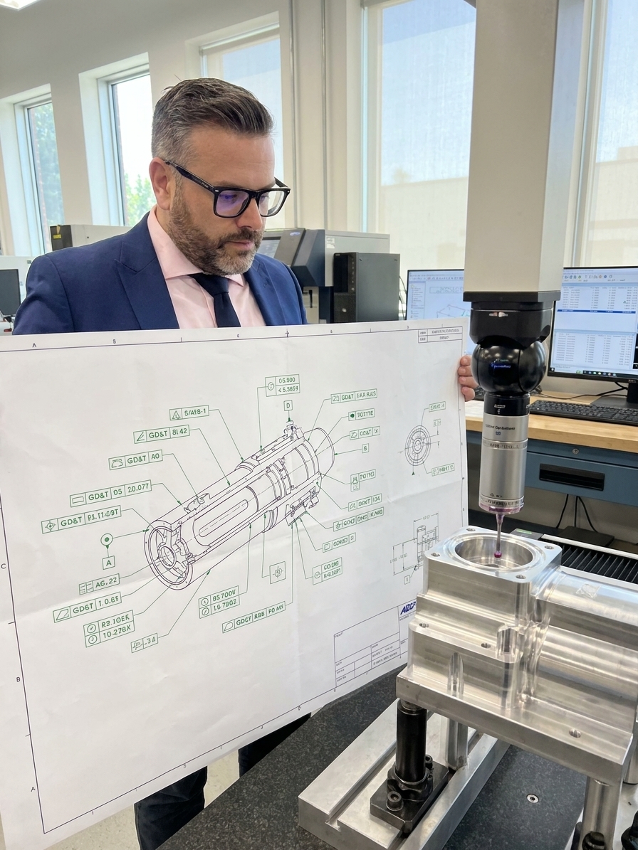
Geometric Dimensioning and Tolerancing was engineered to eliminate ambiguity from the supply chain. The ASME Y14.5 standard provides a mathematical framework to communicate exactly how a part must function, replacing imprecise plus-minus tolerancing with defined cylindrical zones, datum reference frames, and material condition modifiers.
In practice, the standard has devolved into a symbol dictionary that practitioners apply without grasping the underlying mechanics. Organisations invest in certification courses and print reference posters for their quality labs. Yet if you place a complex drawing on a table and ask five team members to interpret a multi-segment feature control frame, you will get five conflicting answers.
Three of those answers will be fundamentally wrong. One will be close enough to pass a drawing review but cause failures in production. Only one will be correct, usually belonging to the single subject-matter expert in the plant. This concentration of knowledge is a severe operational risk. I have audited aerospace and automotive plants where impending retirement of one engineer threatened to render the organisation functionally illiterate regarding its own technical drawings.
The False Security of Plus-Minus Conversion
Plus-minus tolerancing creates rectangular acceptance zones. A hole located with a plus-minus tolerance of 0.25 mm can actually be manufactured 0.35 mm diagonally from true position. The corners of the rectangle are further from the centre than the sides, meaning the tolerance band is not uniform. Parts produced in the corners are accepted by inspection despite being further from true position than the linear tolerance implies.
ASME Y14.5 solves this by generating a cylindrical tolerance zone for position callouts. Every point within that cylinder is exactly equidistant from true position. This approach is more restrictive in the corners but more permissive along the axes, perfectly reflecting how a fastener actually clears a mating hole during assembly.
The fatal flaw in many organisations is the quiet conversion of GD&T back into plus-minus arithmetic during tolerance stack-up analysis. Engineers extract a position tolerance, convert it to a linear equivalent, and plug it into a statistical model. They ignore the cylindrical boundary, the bonus tolerance granted at maximum material condition (MMC), and the datum reference frame constraints.
The resulting spreadsheet generates a favourable capability index, and management approves the design. The arithmetic looks rigorous, but it misrepresents the physical reality of the assembly. When the components inevitably fail to mate on the production floor, the discrepancy report highlights manufacturing variation rather than the flawed stack-up logic.
The CMM Black Box
Coordinate Measuring Machines have masked the widespread lack of GD&T knowledge. Modern CMM software automates geometric evaluation. An inspector imports the CAD model, probes the features, and the system reports a pass or fail against the tolerance. When the machine reports a profile deviation of 0.05 mm against a 0.25 mm tolerance, everyone nods and moves on.
The danger is hidden in the algorithm. If you ask that same inspector which datum precedence was applied, or whether the simultaneous requirement rule was activated, you will frequently get a blank stare. The machine made the engineering decision, and the human blindly trusted the output.

This blind trust becomes catastrophic when software is configured incorrectly. At a medical device manufacturer, a CMM reported profile-of-a-surface callouts as non-conforming across an entire production run. The quality engineer halted production, generated nonconformance reports, and initiated an 8D investigation. Suppliers were blamed, and root cause analysis consumed weeks of engineering time.
Three months later, a detailed audit revealed that the CMM software was evaluating the profile using the wrong datum precedence. No one in the quality department understood GD&T well enough to question the machine earlier. The organisation had outsourced its engineering judgement to a software algorithm, resulting in a stopped line and a severely damaged supplier relationship.
Datum Selection and Functional Assembly
Datum selection is the most critical engineering decision on any drawing, yet it is the most frequently mishandled. Datums establish the reference framework for all geometric tolerances. The principle is absolute: datums must reflect how the part is physically located and constrained in its final assembly. The primary datum should be the mating surface that establishes the most critical reference.
When an engineer assigns the wrong datum features, the specified tolerances become functionally meaningless. A position tolerance referenced to incorrect datums may be verified perfectly by the CMM. The inspection report claims 100 percent conformance. The customer, however, will experience 100 percent failure when attempting to assemble the component.
No one can explain the discrepancy because the drawing looks flawless. The symbols are drawn correctly, the tolerance values are tight, and the CMM results are clean. The root cause remains hidden because organisations rarely audit the functional logic behind the datum selection, only the numerical output on the inspection report.
Correct Datum Selection Logic
- 01Functional Assembly IdentificationAnalyse exactly how the part mates, locates, and bolts to the next assembly level.
- 02Primary Datum AssignmentAssign the feature that establishes the primary mating plane, constraining three degrees of freedom.
- 03Secondary Datum AssignmentSelect the feature that aligns the part, constraining two additional degrees of freedom.
- 04Tertiary Datum AssignmentDefine the feature that stops final rotational or linear movement.
This failure mode accelerates in environments utilising 3D Model-Based Definition (MBD). Without a traditional 2D drawing explicitly stating feature control frames, datum selection is often delegated to a CAD designer focused on modelling geometry. The datum reference frame becomes a software convention rather than a functional engineering requirement. The physical basis for the reference frame is entirely lost.
Supplier Verification Beyond the Print
Most supplier-customer quality disputes trace directly back to a GD&T communication failure. The customer engineers a drawing with strict position and profile callouts. The supplier manufactures the part according to their own interpretation of those symbols. The customer inspects the parts using their internal interpretation. The mathematical interpretations differ, and the parts are rejected.
Quality engineers from both organisations meet, brandishing copies of the ASME standard to defend their positions. The meeting stalls. The dispute escalates to management. Months pass, consuming engineering resources. Eventually, the customer issues a concession to accept the non-conforming parts, completely undermining the integrity of the IATF 16949 or AS9100 quality management system.
GD&T is not a drafting standard; it is a communication protocol that demands verification before production begins.
Issuing a drawing is not a one-way communication. Organisations that succeed treat GD&T as a protocol requiring a handshake. During the APQP process, they review the supplier's inspection plan. They compare the supplier's CMM programming against their own datum reference frames. They verify that the supplier correctly understands bonus tolerances before a single chip is cut.
Resolving Supplier Interpretation Risk
Standard Drawing Release
- CAD model and drawing sent directly to supplier portal.
- Supplier programs CMM based on internal assumptions.
- Interpretation gaps remain hidden until first article inspection.
- Disputes arise during PPAP, halting production ramp-up.
Verified Communication Protocol
- Drawing released alongside an agreed measurement strategy.
- Supplier CMM programme validated against customer datum logic.
- Bonus tolerance application aligned prior to tooling cuts.
- PPAP submission proceeds with mathematically aligned data.
Structuring Organisational Fluency
The financial cost of GD&T illiteracy is hidden in scrap variance accounts and overhead absorption. Parts are rejected for failing to meet tolerances that were incorrectly specified. Functional components are reworked to satisfy an irrelevant geometric constraint. Field failures occur because parts that conformed to a faulty drawing did not function in the final assembly.
Organisations that master this language share distinct structural traits. They empower a GD&T champion, typically a senior engineer, to review and approve every drawing before release. This role acts as a safeguard against functional illiteracy. They also mandate rigorous training for inspectors, machinists, and suppliers, refusing to assume that a single certification course is sufficient.
These organisations conduct blind measurement studies. They require multiple inspectors to measure the same part independently, comparing results to identify interpretation discrepancies before they metastasise into production disputes. They maintain internal drafting standards that document their datum selection philosophy and establish rigid boundaries for ambiguous standard provisions.
Finally, they actively audit their CMM algorithms. They verify that the software evaluates geometric boundaries correctly, applies bonus tolerances appropriately, and respects datum precedence. They refuse to blindly trust the machine. The symbols on your drawings are either your most precise communication tool or the most expensive source of institutionalised confusion you possess.