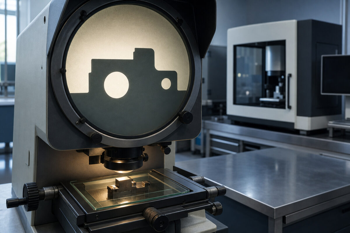
Walk into most inspection labs today and you will find a vision system sitting where an optical comparator used to be. Purchasing approved it, engineering specified it, and the supplier demonstrated it beautifully on a turned aluminium pin with a sharp, clean edge. Then production begins, and operators return with parts that have burrs, radii, mould flash, or surfaces that scatter light in directions the demo part never did.
I am not against vision systems. They are the correct choice for a great many applications, and I have specified them repeatedly throughout my career in automotive and aerospace quality. But the decision must be driven by what the drawing actually demands, not by what looks modern on a capital request. Edge definition, surface interaction, and the physics of transmitted versus reflected light all matter more than pixel count.
When the tolerance zone is tight and the edge is ambiguous, the optical comparator frequently produces more trustworthy data. The instrument must serve the tolerance, not the procurement schedule. Understanding why requires examining the actual physics of how these machines interpret the physical boundaries of a manufactured component.
Edge Definition at the Glass
A comparator projects a magnified silhouette of the part onto a screen. The edge you see is formed by light being blocked by the physical material of the component. That boundary is direct and uncompromising. The light either passes or it does not. A vision system, by contrast, must interpret a gradient of pixel intensities and decide, algorithmically, where the edge sits.
That algorithm has thresholds, filters, and parameters that someone selected, often without full understanding of the part’s surface behaviour. Consider a ground shaft with a slight burnishing at the transition from diameter to shoulder. The vision camera sees a gradual change in grey levels across that transition zone. Depending on the edge detection algorithm and its sensitivity settings, the reported edge could shift by several microns between two identical parts.
The comparator shows you a shadow with a crisp boundary because the geometry itself creates that boundary at the projection plane. This is not a theoretical concern. On aerospace actuator components where shoulder-to-shoulder dimensions carry tolerances of plus or minus ten microns, that algorithmic uncertainty directly consumes your tolerance budget. The comparator’s edge sits where the physical material stops, full stop.
Transmitted Light and the Physics of the Silhouette
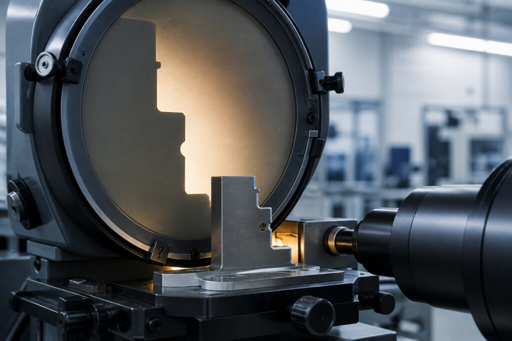
Optical comparators use transmitted light for through-measurements and reflected light for surface features. The transmitted light method creates a true first-angle or third-angle projection of the part profile, depending on the screen arrangement. That projection is geometrically faithful because it follows the same principles as the drawing views themselves. What the designer drew is what the operator measures.
Vision systems use back lighting for silhouette work, but the camera’s finite depth of field introduces complications that the comparator avoids. A thick part measured under back-lit vision can show edge positions that depend on the part’s tilt and the lens focal plane. The comparator’s parallel projection light collimates through the full thickness of the component, presenting a silhouette that integrates the profile consistently regardless of minor thickness variations.
Thin stamped parts present a particularly good case for the comparator. The sheared edge creates a slight taper, and the burr casts its own shadow under the collimated light. An experienced operator can see these features and account for them. A vision system reports a single edge position with no contextual information about what the edge actually looks like, and that context matters enormously when troubleshooting a stamping process that is drifting.
Operator Variation and the Honest Shadow
The standard criticism of optical comparators centres on operator variation. One inspector aligns the crosshair differently from another. One picks the edge where the shadow begins to darken; another waits for full blackness. These are real sources of variation, and I will not pretend otherwise. But what the criticism often misses is that vision systems simply relocate that variation, they do not eliminate it.
A vision system’s operator chooses the lighting type, the intensity, the algorithm, the region of interest, and the acceptance parameters. Change any one of those and the dimensional result moves. The variation has not been removed; it has been hidden behind a software interface that makes it harder to audit. When a dispute arises about a borderline dimension, the comparator allows two inspectors to look at the same shadow simultaneously and discuss what they see.
Comparator Auditability vs. Vision System Variation
Vision system variation
- Algorithm sensitivity and edge detection thresholds
- Lighting type and intensity selected by the operator
- Region of interest and parameter configuration
- Result presented as a number without visual context
Comparator auditability
- Physical shadow visible to multiple inspectors at once
- Single collimated light path with no software filters
- Edge defined by physical material, not algorithm
- Reasoning transparent and open to direct discussion
Managing Variation Through Clear Work Instructions
My approach has been to write clear, specific measurement instructions for comparator work. Specify the screen magnification, the alignment method, the lighting intensity, and the edge-picking technique. Train the operators against those instructions and verify their consistency. This addresses operator variation directly and honestly, rather than assuming the machine has solved it for you.
The decision between comparator and vision should begin with the tolerance band and the feature type. Tight positional tolerances on prismatic parts with well-defined edges suit vision systems well, particularly when throughput demands automation. The vision system finds the edges quickly, calculates the positions, and reports deviations against the drawing with minimal operator involvement. That is a legitimate, valuable use of the technology.
However, parts with machined features that include radii blends, chamfer transitions, or thread forms need careful consideration. The vision system struggles where the edge definition becomes ambiguous, and the algorithm makes silent decisions that may not match the functional intent of the feature. A comparator allows the operator to pick the tangent point of a radius using the screen crosshair, applying the same geometric principle that the designer used when dimensioning the part.
The variation has not been removed; it has been hidden behind a software interface.
Surface Feature Verification Under Reflected Light
Comparators equipped with surface illumination remain uniquely useful for inspecting engraved markings, surface defects, and machined features that do not create a profile change. The reflected light system on a comparator is simpler than a vision system’s lighting array, and that simplicity is an advantage. One light source, one angle, one magnification. The operator sees exactly what is illuminated and can rotate the part to examine features from different orientations without reconfiguring anything.
Vision systems offer ring lights, coaxial illumination, polarising filters, and directional arrays. Each has merit, but each also introduces a variable. When an inspector at a vision station reports a surface anomaly, the first question is always about the lighting configuration. Was the ring light at full intensity? Was the polariser engaged? The same anomaly may appear or disappear depending on those settings, and that uncertainty undermines confidence in the inspection result.
For first-article inspection of complex machined housings, I routinely specify comparator verification of specific surface features alongside the CMM dimensional checks. The comparator catches things that coordinate measurement misses because the probe takes discrete points while the comparator shows the continuous surface. Burr remnants at drilled hole exits, tool marks at pocket corners, and blend irregularities at machined radii all show up clearly under the comparator’s surface light.
Selecting the Correct Inspection Method
- 01Identify feature typeDetermine if the feature is a prismatic edge, a radius blend, a thread form, or a surface marking.
- 02Assess edge ambiguityEvaluate whether the physical edge is sharp and clean, or if burnishing, tapers, and burrs create gradient zones.
- 03Review tolerance budgetDetermine if the feature tolerance is tight enough that sub-micron algorithmic uncertainty will consume the budget.
- 04Select the instrumentMatch the tool to the physics of the edge: vision for clean prismatic parts, comparator for ambiguous geometries.
Maintenance and Calibration Fundamentals
A comparator that produces poor results is almost always a comparator that has been poorly maintained. The optical surfaces collect dust, the screen accumulates handling oils, and the light source degrades over time. These are not exotic failure modes; they are predictable consequences of daily use in a shop environment. The maintenance routine is straightforward but must actually be followed.
Clean the projection lens and the stage glass daily with lens tissue and isopropyl alcohol. Check the screen for scratches and discolouration, both of which affect contrast and edge clarity. Verify the magnification accuracy using a calibrated reticle or a precision line standard at least monthly. The stage scales require calibration against a known length standard, and the squareness of the stage axes must be confirmed using a precision square or optical polygon.
Light source alignment matters as well. The lamp filament must sit centred in the optical path, or the illumination becomes uneven and the edge definition suffers on one side of the screen. Check this by projecting a precision pin gauge and comparing the shadow sharpness at opposite edges of the screen. Uneven sharpness indicates a lamp alignment issue that will bias dimensional results if left uncorrected.
Building Inspector Competence on Legacy Equipment
The most pressing threat to comparator effectiveness is not technological obsolescence but operator unfamiliarity. New inspectors arriving from technical colleges have trained primarily on vision systems and coordinate measuring machines. The comparator looks archaic to them, and they reach for it last, if at all. That is a failure of training, not a failure of the instrument.
My inspection teams spend dedicated time on comparator technique regardless of what other equipment is available. Reading a silhouette correctly, picking an edge consistently, and using the screen protractor for angular measurements are all skills that require supervised practice. I pair new inspectors with experienced operators for their first weeks of comparator work, and I verify their measurement consistency against known standards before they release parts independently.
The comparator teaches something that vision systems obscure: the relationship between the physical part and the dimensional result. When an operator sees the shadow move as the part shifts on the stage, the connection between geometry and measurement becomes tangible. That understanding carries over into every other inspection method they use. Inspectors who have mastered the comparator make better decisions at the vision system and the CMM because they understand what the instruments are actually measuring.