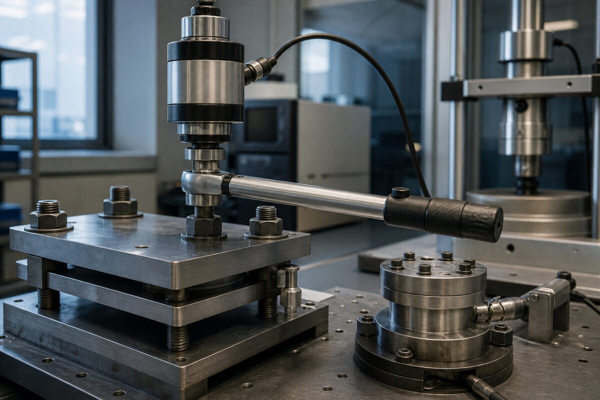
The Tool Certificate Is
Not the Joint
Walk through any assembly facility and you will find calibration
certificates laminated and hanging from DC nutrunners like talismans.
Operators trust them implicitly. Quality engineers cite them during
audits. Yet joints still loosen in the field, and nobody can explain
why, because the certificate confirms only that the tool produced a
defined output against a calibration stand in a controlled laboratory.
That stand bears no resemblance to the actual joint — different
stiffness, different friction characteristics, different temperature,
different surface finish.
I learned this distinction the hard way on a driveline programme
early in my career. Every tool on the line held a valid certificate.
Every audit passed. Yet warranty claims for loose fasteners kept
arriving months after launch. The certificate told us the transducer was
accurate. It told us nothing about what happened when that transducer
drove a bolt into a cast aluminium housing with threads cut that
morning, coated with residual machining fluid, and galled against a
stamping with completely different mechanical properties.
A torque verification programme must bridge this gap deliberately.
The tool certificate is your starting point, not your conclusion. What
matters is the residual condition of the joint after the tool has done
its work and the assembly has settled into its operating state.
Building
a Residual Torque Audit That Means Something
Residual torque audits get performed badly more often than they get
performed well. The typical approach — sending a technician around with
a dial wrench to twist fasteners and record readings — generates numbers
that look reassuring on a report but correlate poorly with actual joint
integrity. The method misses the fundamental physics. Residual torque is
the torque required to overcome static friction and restart movement in
an already-fastened joint. It is not the same as the torque that was
originally applied, and it never will be.
Proper residual audits demand a defined method and a trained hand.
The audit wrench must break the fastener loose in the tightening
direction, not the loosening direction, because you want to measure the
friction holding the joint in its current state, not the friction
required to unwind it. Movement must be detected mechanically — the
first movement, not a quarter-turn later. Reading the peak at first
movement gives you the residual value. Anything beyond that is measuring
something else entirely, and that something else has no predictive value
for whether the joint will hold.
The frequency and sample structure of your audit matter as much as
the technique. Auditing every fastener on a line every shift creates
noise without insight. You end up chasing variation that does not matter
whilst missing systematic shifts that do. Build the audit around joint
criticality, material pairing, and historical failure patterns. Audit
the joints that can cause safety issues or field returns more
aggressively, and audit the joints with known relaxation behaviour —
soft materials, composite interfaces, thermal expansion mismatches — on
a cadence that catches drift before it becomes a warranty claim.
Angle of Turn:
What Torque Alone Cannot Tell You
Torque is a proxy for tension. That is the uncomfortable truth that
most assembly specifications refuse to acknowledge openly. When you
apply torque to a fastener, you are actually trying to stretch the bolt
to create clamp load. The torque-tension relationship depends on
friction, and friction is the most variable quantity in any threaded
assembly. Thread friction, bearing surface friction, and the friction
between the clamped parts themselves all conspire to make torque a blunt
instrument for controlling clamp load.
Angle of turn measurement addresses this directly. Once a fastener
has snugged down against the joint — what we call the snug condition —
additional rotation stretches the bolt along a predictable curve
determined by the pitch of the thread and the stiffness of the clamped
stack. The relationship between angle and tension is far more stable
than the relationship between torque and tension, because it sidesteps
friction almost entirely. The bolt behaves like a very stiff spring, and
springs follow Hooke’s law with admirable consistency.
Implementing angle control requires knowing where snug occurs, and
that is where many programmes falter. Snug torque must be established
empirically for each joint, not assumed from a handbook value. Run a
series of tests where you tighten to snug, mark the angle, then continue
to target torque while measuring the additional rotation. If the angle
of turn past snug falls within a narrow band across multiple samples,
the joint is well-behaved and angle control will give you reliable clamp
load. If the angle scatters wildly, the joint has a friction problem or
a geometry problem that no tightening strategy will fully resolve.
Modern DC nutrunners with integrated angle encoders make this
approach accessible on the production floor. The tool can be programmed
to run to a snug torque, then switch to angle control for the final
tighten, logging both values for every cycle. This dual strategy catches
individual joints that behave abnormally — a cross-threaded bolt will
reach snug torque at an impossible angle, and the tool can flag it
immediately rather than passing it downstream.
Transducer
Calibration: Traceability Without Complacency
Calibration of torque transducers follows established standards, and
most facilities maintain traceability to national standards through a
documented chain. This is necessary and good. It is also where many
quality programmes stop thinking. The calibration certificate confirms
transducer accuracy at specific torque values, applied under specific
conditions, at a specific point in time. None of those conditions
persist on the production floor.
Temperature drift affects strain-gauge transducers measurably. A
transducer calibrated at laboratory temperature will read differently on
a cold assembly line in January and on the same line during a heatwave
in July. Mechanical shock — a nutrunner dropped onto concrete, a
transducer bumped against a fixture — can shift the zero point or
introduce non-linearity that the certificate never captured. Cable flex
on handheld devices creates additional resistance changes that the
calibration laboratory never sees.
A robust verification programme includes intermediate checks between
formal calibrations. These do not replace accredited calibration, but
they catch drift before it becomes a problem. A simple joint simulator —
a calibrated test joint with known characteristics — allows operators to
verify that the tool still behaves as expected at the start of each
shift. Document the readings, set control limits based on the
transducer’s specification, and investigate any reading outside those
limits immediately. The intermediate check costs minutes per shift. The
alternative is discovering drift during a customer audit or, worse,
during a field failure investigation.
Joint
Relaxation: The Enemy You Cannot Tighten Away
Some joints lose clamp load simply by existing. Soft materials under
compression creep. Paint coatings flatten under pressure. Gaskets flow.
Threaded interfaces with dissimilar metals undergo micro-slip under
vibration. All of these mechanisms reduce residual clamp load over time,
and no amount of additional torque at assembly will prevent the loss —
it will only delay it, sometimes only marginally.
Aluminium housings paired with steel fasteners represent the classic
relaxation problem. The aluminium creeps under the bolt head and along
the thread engagement, particularly at elevated operating temperatures.
A joint torqued correctly on Monday morning may retain only a fraction
of its initial clamp load by Friday, and the assembly may not see its
worst thermal exposure until it reaches the customer’s operating
environment. Composite structures exhibit even more dramatic relaxation
behaviour, as the matrix material flows under sustained clamp load and
the fibre architecture redistributes stress.
Managing relaxation requires measuring it, not guessing at it. Build
test assemblies with instrumented bolts or load washers and track clamp
load over the expected thermal and vibration cycle the product will see
in service. The data tells you how much clamp load you will lose and how
quickly. Only then can you specify assembly torque that leaves enough
residual margin after relaxation to keep the joint functional throughout
its design life. Some joints may require a retightening procedure after
a settling period. Others may need Belleville washers or flanged
fasteners to distribute load over a larger bearing area and reduce
contact pressure on the soft material. The solution follows the
measurement, never the other way round.
Pulling the Programme
Together
A torque verification programme that prevents joint failures rests on
three pillars working in concert. First, you establish that the tools
produce known output through traceable calibration and intermediate
checks. Second, you verify that the joints actually achieve the intended
clamp load through residual torque audits and angle monitoring that
reflect real-world conditions. Third, you account for the time dimension
through relaxation testing that predicts what the joint will look like
after weeks or months in service, not just seconds after the nutrunner
clicks off.
Documentation ties these together but does not substitute for any of
them. I have seen facilities with immaculate torque records and
catastrophic joint failures because the records documented a process
that was never actually under control. The audit form was filled out
perfectly. The readings were within specification. The specification
itself was wrong for the joint, the material, and the operating
environment. Good documentation of a bad process produces confident
failure.
Train your engineers and technicians to think physically about what
is happening inside the joint. The torque wrench is not applying torque
— it is stretching a bolt to clamp two surfaces together, and the torque
reading is merely the most accessible indicator of that stretch. When
something goes wrong, the first question should always be: what happened
to the clamp load? Not: was the tool calibrated? The tool certificate
answers a narrow question. The clamp load question addresses the thing
that actually matters, and it requires understanding the joint as a
mechanical system, not just a torque target on a drawing.
Peter Stasko is a Quality Director with 25+ years of experience
leading quality management systems across the automotive and aerospace
industries.